Jabiru
..............................................................................................................................................................................................................
STOLLSPEED VG FEATHERS FLIGHT TESTING DATA
JABIRU -J120 test aircraft
APPLICABLE TO J160 LSA SP
Design factors for placement is quite critical on this wing section for the VG’S to be effective
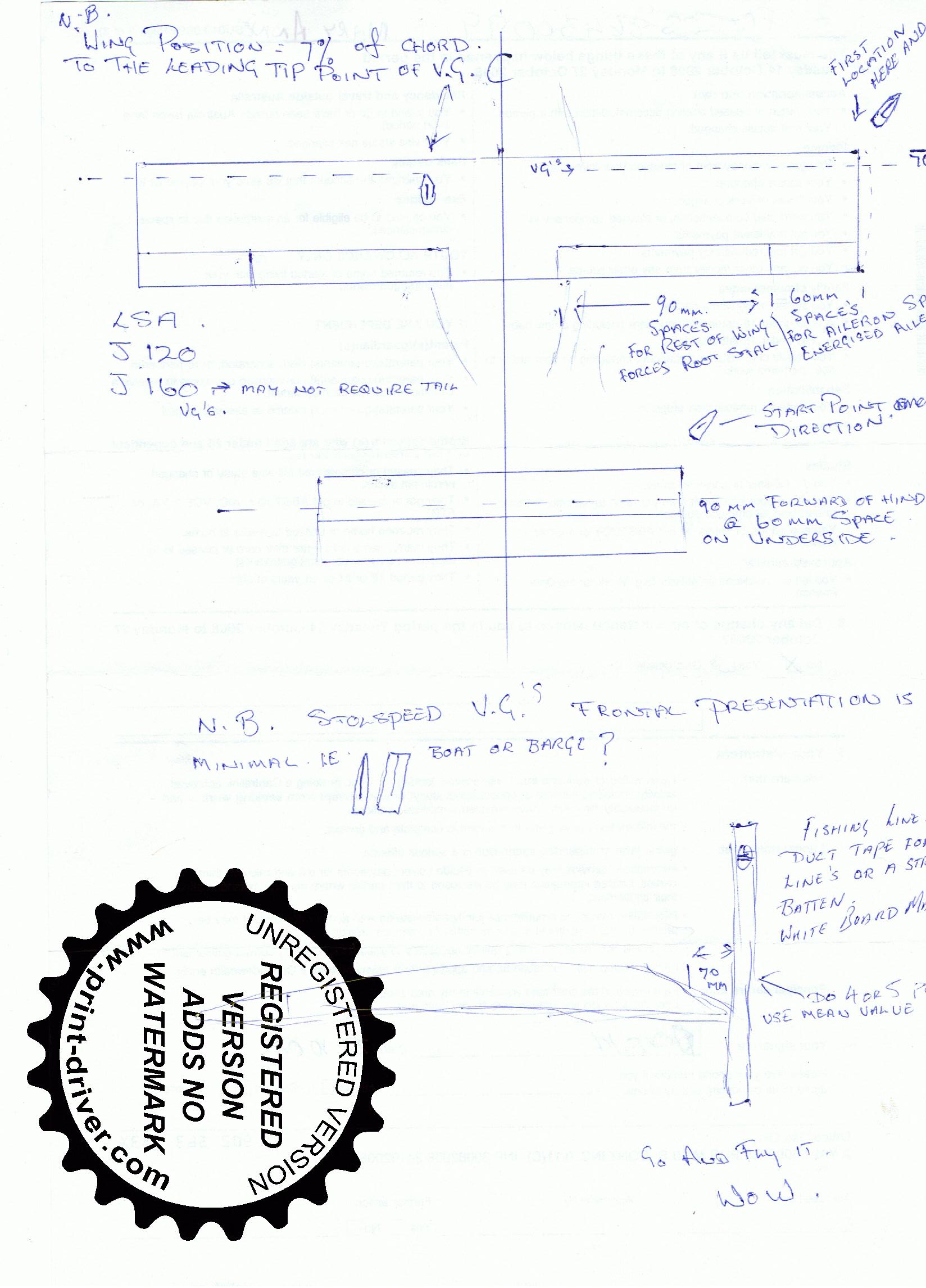
WING; the very leading edge point at a line measured 70mm aft of the leading edge, with spacing from wing tips 60mm apart for the aileron span and the 90mm for the rest of the span to the wing root, this forces a root stall first as well as increased aileron effect. Start wing tip with the vg pointing away from the fuselage. This configuration will reduce stall 5 kts, no measurable drag component was evident. This was also tested on a J160 which also reduced stall 5 kts and could maintain level flight at 50kts with control land gently and a solid controllable feel was achieved. Shorter take off and landing, also climb rate was improved about 200ft p/min on the J160.
The horizontal stabiliser was done as well on the J120 at aft of a line 90mm forward of the elevator hinge but on the underside with the VG’S placed at 60mm spacing starting 50mm inboard from the tip.
Rudder a line parallel to the hinge line 30mm forward and horizontal use a level there is no apposing angle on this part as angle of attack increases so does the vg become more active when you most need it, thus presenting no drag in cruise.
Fight testing the J120 was simply amazing a full 5 kt reduction is stall speed, but the real win is low speed ops, lower power to maintain low airspeeds, it can fly solidly at 50 kts with control authority.
Take off distance is reduced by 100 mtrs at gross
Climb rate has improved by 250 ft per min at gross
Landings are very light and gentle no more sudden arrivals with earth.
Stall warning screams forever now, stall occurs at a much steeper angle and breaks clean but sharper due to the low speed, ailerons were effective all the way as was the rudder, no tendency to drop a wing, in any configuration in fact a full power high speed turn was held until all i had was a mush out falling out level wings on 3 occasions.
Overall I found my great little airplane to be even better and safer for all operations, especially at gross weights, great climb and maintains altitude at reduced power settings which proves to me that my wings are working at maximum efficiency, I have concluded that I would not want to operate my airplane without the VG’S it fly’s better safer and more efficiently, I was sceptical as well as being an independent operator but I feel I must share this info with other Jab flyers, make your great plane even better and best of all safer with no measurable speed loss
The J160 reported also a 5 kt stall reduction with vg’s fixed at the locations described in my report t/o run and low speed ops all much better with very gentle landings, he already had a set of vg’s which were of a draggy design square footplate instead of a point on this wing the footplate total is 1.4 mtrs compared with 150mm of frontal presentation of the stollspeed vg’s also the radius of the stollspeed VG’S have a slight Radius at the base and fits the Jab perfectly like tailor made , so the J160 owner will refit with these stollspeed units and report back.
I was going to present all the test data speed runs temp alt you name it, but at the end of the day this is what you will get 5 kts off the stall and great low speed handling shorter take off and landing better climb, this is what counts and a lot of mumbo jumbo does not explain the benefit in a nutshell they are great, now go flying.
Steve, South Australia
The Stolspeed VGs are placed with the front tips of the VGs 70mm back from a vertical at the leading edge of the wing. Starting at the wingtip, the the first 15 VGs are at a spacing of 60mm, then 90mm for the rest of the wing. Templates are provided to set the spacing and angle to the airflow. For the tail, place the VGs on the under side of the horizontal stabilizer, with the front tips 90mm in front of the hinge line, at a spacing of 60mm.

(The 'unregistered' watermark has nothing to do with this drawing by Steve. It just applies to the software that converted the drawing from pdf to jpeg.)